
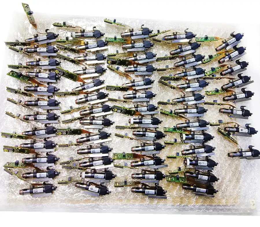
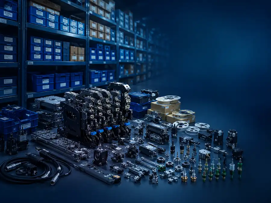
An ASM SIPLACE X-Series S model name tells you the gantry count — not the installed configuration. Two X4 S machines, for example, can carry the same model name and still have different published output, usable feeder capacity and component capability. Head package, feeder layout, conveyor mode and machine generation determine whether the configuration fits the line.
The checks below cover both selection and used-machine verification. For the full model family, see the ASM SIPLACE X-Series S overview.
Model Name Is Only the Starting Point
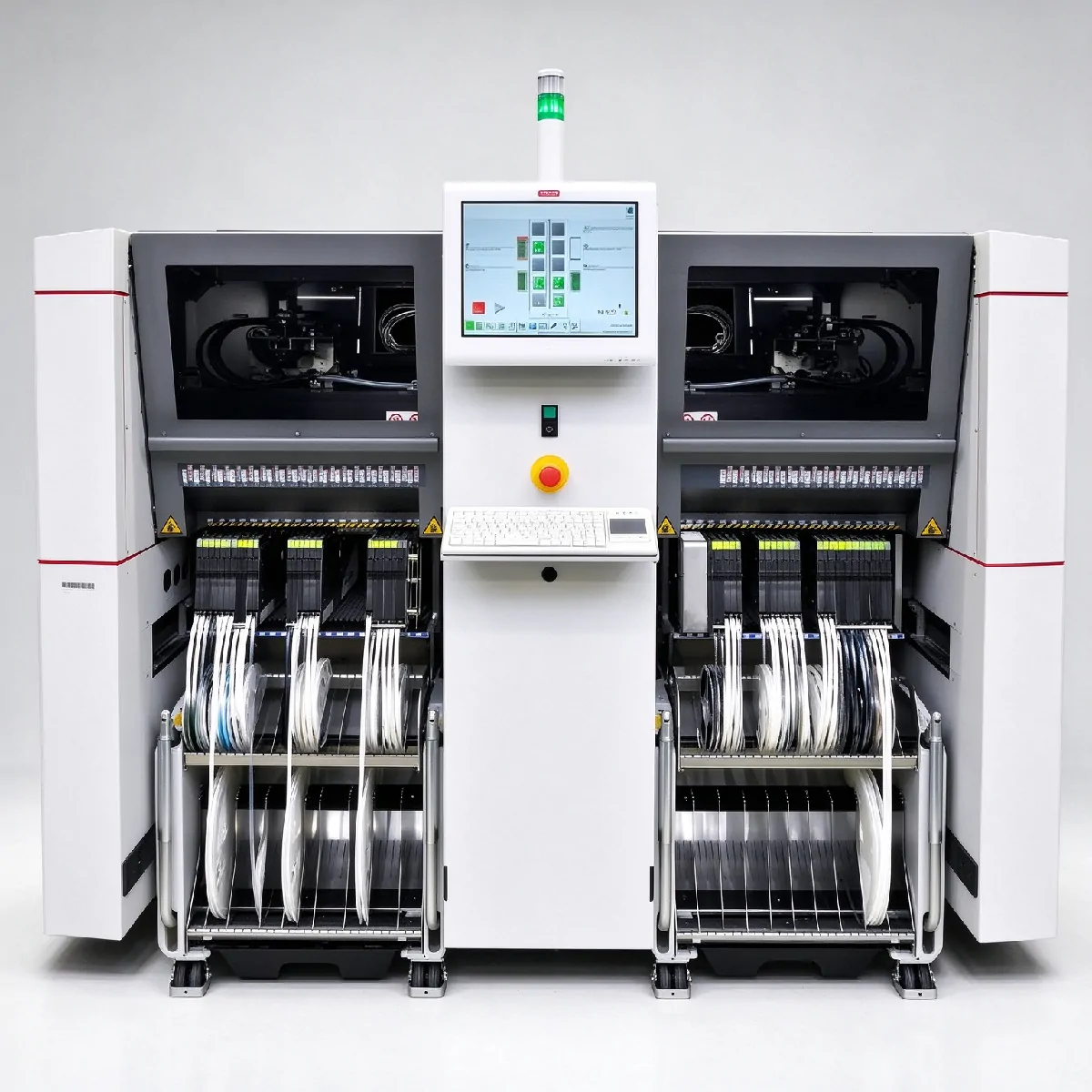
X2 S, X3 S and X4 S primarily tell you gantry count: 2, 3 and 4. They do not tell you which placement heads are installed, how feeders are arranged, which conveyor mode is configured, or which generation of hardware and software the machine uses.
| Model | Gantries | Published benchmark (CPH) | Published IPC (CPH) | Feeder positions (8 mm) |
|---|---|---|---|---|
| X2 S | 2 | 75,000 | 65,000 | up to 160 |
| X3 S | 3 | 112,500 | 97,500 | up to 160 |
| X4 S | 4 | 150,000 | 130,000 | up to 160 |
| X4i S | 4 | 172,000 (later generation) | 146,000 (later generation) | up to 148 |
Performance figures are published platform values under specified head and conveyor configurations. Verify the installed configuration on the actual machine.
Used X-Series S units exist across multiple hardware and software generations. The original SIPLACE X2/X3/X4 and X-Series S are separate platforms; head terminology, feeder compatibility and software features are not universally interchangeable.
Choose Gantry Count by Actual Workload
Gantry count affects parallel placement capability, not linear speed. Before choosing between X2 S, X3 S and X4 S, answer three questions:
How many placements must be completed per board?
Which components consume most of the placement time?
What cycle time must the placer meet to avoid becoming the line bottleneck?
If placement is not the line bottleneck, a two-gantry X2 S may already meet the required cycle time. Adding gantries beyond that point does not increase line output.
For model-level specifications, see the full X2 S, X3 S and X4 S specification pages.
Head Package Changes More Than Speed
Gantry count defines the platform’s parallel placement potential. The installed head package strongly influences how much of that potential the configuration can actually reach.
Why can two SIPLACE X4 S machines have different rated output?
Placement performance depends on head combination, head position and conveyor configuration. The 2021 SIPLACE X-Series S specification shows the same machine model producing different published IPC and benchmark values when the head mix changes.
| Example configuration | IPC | Benchmark | Note |
|---|---|---|---|
| X4 S: four C&P20 P2 heads | 130,000 | 150,000 | Maximum standard X4 S speed configuration |
| X4 S: two C&P20 P2 + two CPP_L | 102,400 | 119,000 | Same X4 S model, materially lower published output |
| X4i S: four C&P20 P2 heads | 146,000 | 172,000 | Later high-output X4i S configuration |
| X4i S: two C&P20 P2 + two CPP_L | 112,950 | 133,000 | “X4i S = 172k” is not true for every head package |
Source: ASM SIPLACE X-Series S specification, 2021 edition. Values are published platform data and depend on installed head combination and conveyor configuration.
Model name and brochure speed alone are not enough to value a used machine. The head package must be specified.
Used-machine note: Older and newer documentation may use different head-family names. Verify the physical head label and part number on the machine itself.
Head naming across generations
| Older terminology | Later documentation | Core function |
|---|---|---|
| SpeedStar (C&P20 P2) | CP20 | High-speed collect-and-place |
| MultiStar (CPP) | CPP | Flexible pick-and-place, wide component range |
| TwinStar (TH) | TWIN | High-force / large / odd-form component placement |
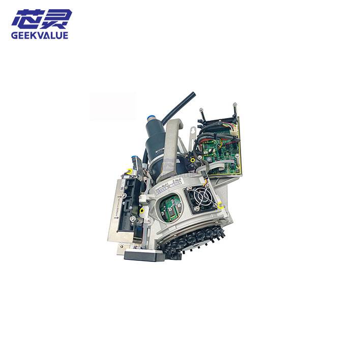
Head selection affects speed, placement mode, component range and spare or maintenance requirements. If the installed head package is unclear, ask for head labels and part numbers before comparing quotations.
Conveyor Mode and PCB Geometry Must Be Verified
The X-Series S supports different conveyor concepts. They are not interchangeable, and the difference affects cycle time.
Synchronous mode: two boards are treated as a common panel and processed together.
Asynchronous mode: one board is placed while the other lane transports the next board, reducing transport loss on short-cycle products.
i-Placement: two heads work simultaneously and independently on the corresponding conveyor side.
On supported i-Placement configurations, Borrow Performance can help balance unequal workload between lanes.
Why 380 mm is a full-function boundary, not a hard limit
Per 2021 specifications, X4i S delivers full i-Placement functionality with PCBs up to 380 × 320 mm. Longer boards may still be supported depending on conveyor and long-board configuration, but full i-Placement parallel operation may no longer apply.
| Configuration | Flexible dual conveyor envelope |
|---|---|
| X2 S / X3 S / X4 S | up to 450 × 320 mm per lane |
| X4i S | full functionality up to 380 × 320 mm |
Before choosing X4i S for a large-board product, confirm:
PCB length and width
whether two different boards run simultaneously
required cycle time
whether full i-Placement functionality is actually needed
For configuration details, see the X4i S i-Placement conveyor configuration. For how conveyor mode changes actual cycle time, see rated CPH vs actual output.
Feeder Demand Must Be Calculated Separately
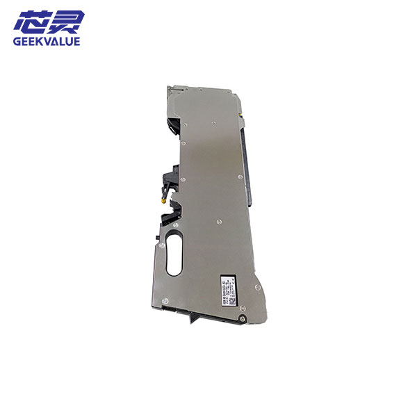
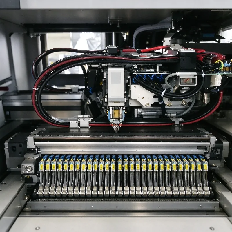
160 feeder positions do not equal 160 physical feeders. Feeder positions are slots on the feeder table. Wider tape consumes multiple 8 mm position equivalents.
| Model | 8 mm feeder positions |
|---|---|
| X2 S / X3 S / X4 S | up to 160 |
| X4i S | up to 148 |
As a rule of thumb, wider tape consumes multiple 8 mm position equivalents. A 16 mm feeder typically occupies 2 positions, and a 24 mm feeder typically occupies 3.
Example mapping:
10 × 8 mm  = 10 positions
 6 × 16 mm = 12 positions
 4 × 24 mm = 12 positions
-----------------------------
20 physical feeders = 34 × 8 mm-equivalent positions
Feeder quantity included with a used machine is commercial information and must be stated separately in the quotation.
Tray supply is configuration-specific. The 2021 family documentation covers MTC, WPC5/WPC6 and JTF-M, but restrictions differ by machine and position.
For feeder options, see SIPLACE X-Series feeders. To map your BOM to feeder positions, send your BOM for feeder mapping.
Published CPH Is Not Board Output
Three different figures are often mixed together:
IPC value: based on IPC 9850 vendor-neutral conditions.
SIPLACE benchmark: measured under ASM machine acceptance test conditions.
Actual board output: depends on the real PCB program, placements per board, head mix, transport mode, feeder layout and line bottleneck.
150,000 CPH benchmark and 130,000 IPC can both be correct for the same X4 S configuration. Neither figure matches the actual production throughput you will achieve on your specific PCB assembly. For the full explanation, see rated CPH vs actual output.
X4 S vs X4i S: Where i-Placement Changes the Decision
The two models differ in feeder capacity, conveyor behavior, PCB envelope and generation-dependent published performance. X4i S is not simply “X4 S but faster.”
X2 S, X3 S and X4 S differ mainly by gantry count, which is covered in the model table above. The comparison below focuses on X4 S and X4i S because both are four-gantry platforms and are the two models most often confused.
| X4 S | X4i S | |
|---|---|---|
| Published placement performance | 150,000 benchmark / 130,000 IPC | 172,000 benchmark / 146,000 IPC (later generation) |
| Feeder positions | up to 160 × 8 mm | up to 148 × 8 mm |
| Dual-lane behavior | flexible dual conveyor | i-Placement |
| Full-function dual-lane PCB envelope | up to 450 × 320 mm per lane | up to 380 × 320 mm |
| Tray / IC supply | Verify installed MTC/WPC/other tray configuration by generation | Verify installed tray/JTF configuration by generation |
| Nozzle changer | configuration-specific | configuration-specific, differs from X4 S in some head setups |
i-Placement is an X4i S platform function and should not be assumed to be available on a standard X4 S configuration.
How the choice usually breaks down:
Wide BOM, high feeder demand → check 160 vs 148 carefully. X4i S has a lower published 8 mm-equivalent feeder-position capacity.
PCB ≤ 380 mm, dual-lane parallel value is high → X4i S i-Placement may justify the choice.
Standard four-gantry throughput is enough, no i-Placement needed → evaluate X4 S first.
Tray supply must be verified on the actual machine — not inferred from the model name.
To compare for a specific board, see the X4 S standard four-gantry configuration and X4i S i-Placement version pages, or request an X4 S vs X4i S comparison.
Used X-Series S: Verify Generation, Heads and Feeders
A used X-Series S quotation should include verifiable machine identity and configuration. Request the following, grouped by category:
Machine identity
Nameplate, serial number and manufacturing year
Station software version
Placement configuration
Head label and part number for every installed placement head
Gantry motion and calibration status
Nozzle changer and installed nozzle magazines
Material handling
Single or flexible dual conveyor configuration
Feeder tables or trolleys and actual feeder part numbers
Tray module type (MTC / WPC / JTF) if included
Proof of condition
Component and PCB camera condition
Vacuum, force and component sensors where fitted
Total machine cycle count / operating hours (where available)
Sample pickup and placement test using representative components
Included accessories listed separately from the bare machine
For model-specific checks, see the ASM SIPLACE X2 S, X3 S and X4i S feeder configuration pages. To request a structured inspection list, request a used-machine inspection checklist.
What to Send Before Selecting a Machine
Send the following, grouped by decision area:
PCB data
PCB dimensions (maximum and minimum)
PCB thickness, weight and single- or dual-lane production
Component and BOM data
BOM with component types, quantities and tape widths (8 / 12 / 16 / 24 / 32 mm)
Tray-fed, stick and odd-form components
Largest component L × W × H and weight
Placements per board and components per board
Feeder and tray data
Current feeder inventory and tray requirements
Production target
Target CPH and cycle time
Line balance target
Current upstream and downstream line cycle if known
Commercial constraints
Budget and delivery expectation
Whether used equipment is acceptable
FAQ
What is the difference between SIPLACE benchmark CPH and IPC CPH?
Benchmark CPH is measured under ASM’s internal machine acceptance test conditions. IPC CPH follows the industry-standard IPC 9850 vendor-neutral methodology. Neither equals actual production throughput on your specific PCB.
Can an X4i S run boards longer than 380 mm?
Yes, depending on conveyor and long-board configuration. Per 2021 specifications, X4i S delivers full i-Placement functionality with PCBs up to 380 × 320 mm. Longer boards may still be supported, but full i-Placement parallel operation may no longer apply.
Are feeders and tray modules included with a used X-Series S machine?
No. Included feeder quantity and tray modules must be stated in the quotation. They are commercial items and are not implied by the model name.
What is the difference between the original SIPLACE X2/X3/X4 and the X2 S/X3 S/X4 S?
They are separate platform generations. Head terminology, feeder compatibility, conveyor behavior and software differ. Confirm the exact generation from the machine identification, serial number, installed hardware and software documentation.
What information should I send before requesting a configuration review?
PCB size, BOM, placements per board and target cycle time are enough to start.