
Feeder capacity is not a secondary specification. It determines whether a machine can actually run a given BOM. X2 S, X3 S and X4 S support 160 × 8 mm feeder locations. X4i S supports 148. The 12-location difference rarely matters for narrow BOMs, but a wide BOM with many wide-tape and tray-fed components can exceed X4i S capacity after mapping — a problem that only becomes visible after purchase if the BOM is not calculated beforehand.
This guide explains how to convert a PCB BOM into SIPLACE X feeder positions, where the common calculation errors come from, and how the result affects machine selection between X4 S and X4i S.
Quick answer:
-
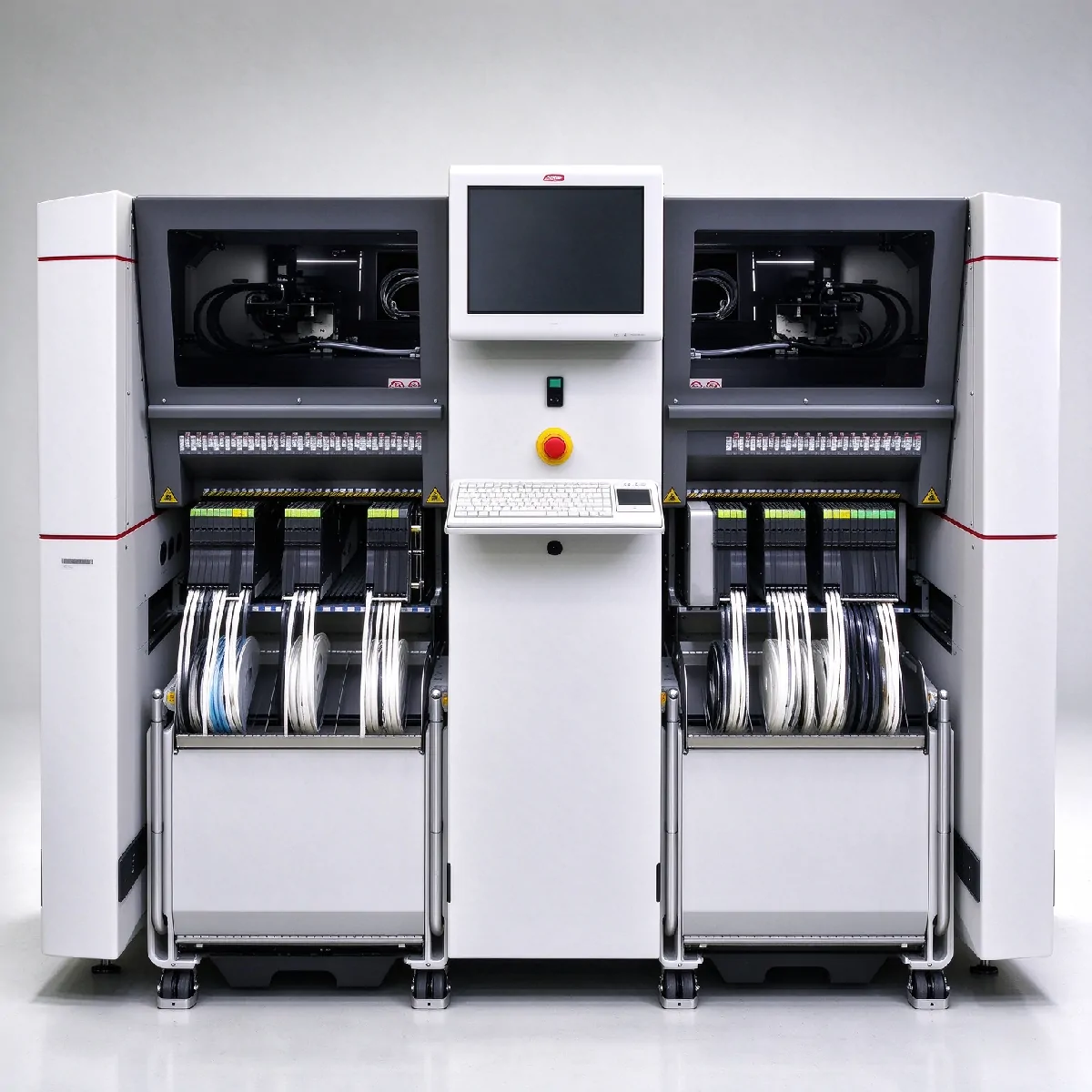
X2 S / X3 S / X4 S: 160 × 8 mm positions
-
X4i S: 148 × 8 mm positions
-
Calculation: list unique feeders → convert feeder width to occupied locations → add tray and special modules → compare with machine capacity
SIPLACE X-Series documentation includes X and Xi feeder variants. Location occupancy is based on the feeder type installed. All values in this guide apply to the SIPLACE X-S S platform.
Why Feeder Capacity Matters Before Selecting a SIPLACE Machine
Feeder layout errors rarely produce immediate failures. They produce silent inefficiencies: a machine ordered with insufficient trolley capacity, a BOM that cannot run without splitting across lines, or an operator who removes feeders mid-production to make room for a tray module.
Three consequences are common:
-
Wrong machine selection. A BOM mapped to 150 positions fits X4 S (160) but exceeds X4i S (148). If the machine is already ordered, the production plan needs rework.
-
Unusable feeder layout. Feeder positions are consumed by the feeders required for each unique component. Two different 8 mm components cannot occupy one active feeder position in the same production setup. The total must reflect the actual BOM, not the component count divided by two.
-
Production limitation at changeover. Without reserve positions, a product change requires removing feeders. This adds setup time and increases the risk of mis-picks.
Feeder capacity planning should happen before the machine configuration is finalized — not after delivery.
Feeder Positions Are Not Calculated by Tape Width Alone
Tape width describes the feeder size. It does not directly give you the number of machine locations consumed.
A 44 mm feeder occupies 5 locations. A wider feeder can consume significantly more. Neither value is a simple division of tape width by 8 mm. The correct figure comes from ASM's published locations occupied table for each feeder type.
This matters because a miscalculation of 5–10 positions can be the difference between a BOM that fits X4i S and one that does not. Most teams that discover a feeder capacity problem do so after selecting a machine — because they estimated positions using tape width instead of the occupancy table.
ASM SIPLACE X Feeder Locations Occupied Table
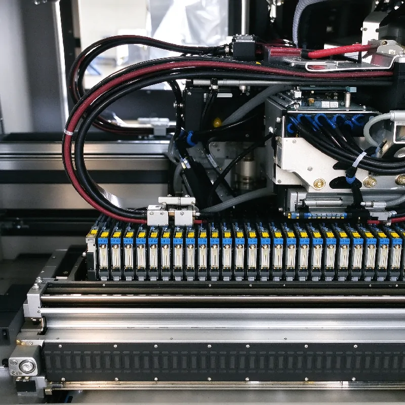
ASM uses both X and Xi feeder variants within the X-Series feeder family. The calculation method is based on the installed feeder type. The table below lists the 8 mm-equivalent locations occupied by each SIPLACE X tape feeder type. All values are based on ASM SIPLACE X-Series S specifications.
| Feeder type | Width (mm) | Locations occupied | Transport increment |
|---|---|---|---|
| 4 mm Xi | — | 1 | 1 mm |
| 8 mm X / Xi | 10.8 | 1 | 1 / 2 / 4 / 8 mm |
| 2 × 8 mm X | 22.6 | 2 | 1 / 2 / 4 / 8 mm |
| 12 mm X | 22.6 | 2 | 4–16 mm |
| 16 mm X | 34.4 | 3 | 4–20 mm |
| 24 mm X | 34.4 | 3 | 4–32 mm |
| 32 mm X | 46.2 | 4 | 4–40 mm |
| 44 mm X | 58.0 | 5 | 4–52 mm |
| 56 mm X | 69.8 | 6 | 4–64 mm |
| 72 mm X | 81.6 | 7 | 4–80 mm |
| 88 mm X | 105.2 | 9 | 4–96 mm |
Source: ASM SIPLACE X-Series S specification. Values are published platform data for the X-S platform.
4 mm Xi feeder geometry differs from standard tape feeders; its width is not directly comparable. Larger feeder sizes (e.g. 104 mm) follow the same official location rules and are available on request.
Two points are worth noting. First, the 16 mm and 24 mm feeders occupy the same number of locations (3), but their transport increments differ. Second, the 44 mm feeder occupies 5 locations — a figure that cannot be derived from tape width ÷ 8, which would give 5.5 or 6 depending on rounding.
How to Map Your BOM to Feeder Positions
The mapping process converts a component list into trolley occupancy. The most common mistake is using components per board as the basis. Feeder positions are counted by unique component, not by component count.
Example: a PCB with 120 × 0402 resistors of the same part number may require only one feeder position if supplied from one 8 mm feeder setup. The requirement scales with the number of unique part numbers and feeder setups, not with the component count.
Step 1: List unique tape-fed part numbers. Group components by packaging type: tape-fed, tray-fed, stick-fed, odd-form. Only tape feeders map to 8 mm position counts.
Step 2: Convert each tape line to locations occupied. Look up each feeder type in the locations occupied table above. Do not use tape width ÷ 8.
Step 3: Add non-tape supply positions. Tray modules, Glue Feeders and other special modules each occupy defined trolley locations. These are covered in the next section.
Step 4: Add changeover and spare positions. Reserve 5–10% spare positions as a practical planning margin for product changeover and future component additions. This is a common industry rule of thumb for high-mix production; adjust the ratio based on your actual changeover frequency.
Step 5: Sum and compare to machine capacity. Compare the total against 160 positions (X2 S / X3 S / X4 S) or 148 positions (X4i S).
If the result approaches 148 or 160 positions, machine selection and feeder layout should be reviewed before purchase. If your total mapped positions exceed 160, you may need to split the BOM across multiple machines or optimize the feeder layout.
Worked Example 1: Tape Feeders Only
| Unique BOM items | Feeder requirement | Locations multiplier | Positions |
|---|---|---|---|
| 10 × 8 mm tape PNs | 10 feeders | ×1 | 10 |
| 6 × 16 mm tape PNs | 6 feeders | ×3 | 18 |
| 4 × 24 mm tape PNs | 4 feeders | ×3 | 12 |
| 2 × 44 mm tape PNs | 2 feeders | ×5 | 10 |
| Total | 22 physical feeders | — | 50 positions |
22 physical feeders consume 50 × 8 mm-equivalent positions. The result fits comfortably on both X4 S (160) and X4i S (148).
Worked Example 2: Adding Special Modules
Feeder capacity is not consumed only by tape feeders. Any module installed on the component trolley also occupies available locations.
Same tape BOM at 50 positions, plus:
| Module | Locations occupied |
|---|---|
| Waffle-pack tray holder | 32 |
| Glue Feeder | 5 |
| Total with tape feeders | 87 positions |
The same 50-position tape BOM becomes 87 positions after adding a tray holder and a Glue Feeder. Still within both machines, but the margin is shrinking.
If your tape BOM already reaches 120 positions, adding a tray holder (32) brings the total to 152 — which fits X4 S (160) but exceeds X4i S (148).
Special Modules Also Consume Available Trolley Locations
Special feeding modules are installed on the component trolley. They do not float outside the feeder system. Each module occupies defined locations from the same 160 or 148 pool.
| Module | Locations occupied |
|---|---|
| SIPLACE Glue Feeder | 5 |
| Linear Dipping Unit X (LDU X) | 9 |
| Waffle-pack tray holder | 32 |
Source: ASM SIPLACE X-Series S specification. The Glue Feeder is as wide as a 44 mm X feeder and requires 5 locations. The LDU X is used for coating flip-chips and CSP components with flux.
Special modules typically require continuous trolley positions and may have installation location restrictions. Always verify layout feasibility against your exact trolley configuration — a module count that fits numerically may still not fit physically.
In production planning, this means: a BOM that fits within 120 tape-feeder positions may still exceed trolley capacity if tray holders, dipping units or other special feeding modules are part of the process. Always include special modules in the position count, not only tape feeders.
160 vs 148 Feeder Positions: X4 S vs X4i S
The 160 and 148 positions refer to the total feeder trolley capacity of the complete machine. For dual-lane configurations, positions are distributed across front and rear trolleys, not per independent lane.
X2 S, X3 S and X4 S support up to 160 × 8 mm feeder locations. X4i S supports up to 148. The difference is 12 positions. Whether that matters depends on your BOM.
| Mapped positions | X4i S (148) | X4 S (160) |
|---|---|---|
| Under 100 | ✅ Feeder capacity unlikely to limit selection | ✅ |
| 100–140 | ⚠️ Verify special modules and spare capacity | ✅ |
| 140–160 | ❌ May exceed after spare positions added | ⚠️ Verify spare capacity |
These ranges are practical planning references, not ASM official thresholds. Actual capacity depends on installed feeder mix, trolley configuration and changeover requirements.
The 148 and 160 figures are maximum theoretical positions. Always reserve spare positions on top of your BOM calculation. A BOM mapped to 142 positions may exceed X4i S capacity after adding a 5–10% changeover buffer.
For the full X4 S vs X4i S comparison, see the X4i S feeder configuration and X4 S feeder configuration pages. For the machine selection framework, see the X-Series S configuration guide.
Why SmartFeeder Features Matter When Buying Used Feeders
For used-equipment buyers, SmartFeeder features provide additional information about setup history and feeder condition. These are condition indicators, not marketing points.
| Feature | Why a buyer should care |
|---|---|
| Unique feeder ID | Machine and setup system can identify the feeder automatically. Verify the ID reads correctly before purchase. |
| Automatic parameter setup | Component pitch and feeder speed are set automatically when the setup program is downloaded. A used feeder with failed electronics cannot use this function. |
| Splice support | Continuous material refill capability. Verify splice sensor function on used units. |
| Contactless data and power | No mechanical connector between feeder and trolley. Reduces wear and setup time. |
| Firmware / EEPROM | A used feeder has electronic condition, not only mechanical condition. EEPROM errors are a known failure mode. |
| Closed-loop feeding | Pickup presentation accuracy is part of feeder condition. Closed-loop control ensures accurate feeding even for 0201 metric placements. |
SmartFeeder features improve setup control and traceability, but they do not reduce the number of occupied locations. A 24 mm SmartFeeder occupies 3 locations, same as a standard 24 mm X feeder.
How to Verify Used SIPLACE Feeders with FVS
BOM mapping determines what feeders you need. FVS testing verifies whether the feeders you are buying actually function. The two steps are separate.
When validating used feeders for your calculated BOM layout, FVS testing verifies critical feeder functionality before they are installed into the machine. It cannot replace part number and compatibility checks.
The SIPLACE X Feeder Verification System (FVS) supports common SIPLACE X feeder formats including 4 mm to 88 mm modules and SmartFeeder 2 × 8 mm and 4–88 mm modules.
FVS can prove:
-
Drive functionality
-
Operating panels and buttons
-
Splice sensor functionality
-
Foil rocker functionality
-
Pickup position repeat accuracy
-
Test reports saved as PDF or CSV
FVS cannot automatically prove:
-
Whether the feeder's tape width and part number/suffix match your BOM requirements
-
Whether the housing has physical damage not visible during electronic testing
-
Which specific physical unit the quotation refers to
-
Long-term production reliability
Request an FVS report or equivalent verification record before purchasing used feeders. Without it, a used feeder is an unverified component.
Before Buying a SIPLACE X Machine, Prepare These Feeder Data
To receive a usable feeder layout recommendation, send:
-
BOM with component types, quantities and tape widths
-
Feeder widths for all tape-fed components
-
Tray-fed, stick and odd-form component list
-
Special module requirements (tray holder, Glue Feeder, LDU X, etc.)
-
Target machine model (X2 S / X3 S / X4 S / X4i S)
-
Production quantity and changeover frequency
FAQ
How many 8 mm positions does a 24 mm SIPLACE X feeder take?
Three. The 24 mm X module occupies 34.4 mm of width, which equals 3 × 8 mm-equivalent locations. The 16 mm X feeder also occupies 3 locations.
How do I calculate feeder positions for my BOM?
List unique tape-fed part numbers, look up each feeder type in the locations occupied table, add positions for tray modules and special feeders, add 5–10% spare as a practical planning margin, then sum against machine capacity (160 for X2/X3/X4 S, 148 for X4i S).
Does a PCB with 120 resistors need 120 feeder positions?
No. Feeder positions are counted by unique component, not by component count. 120 resistors of the same part number may require only one feeder position if supplied from one 8 mm feeder setup. Additional positions are needed only if the same part number requires multiple reels or parallel feeder setups.
Does SmartFeeder change the required feeder positions?
No. SmartFeeder improves feeder identification and setup control, but machine location consumption depends on feeder type and occupied locations. A SmartFeeder 24 mm occupies the same 3 locations as a standard 24 mm X feeder.
Can X4i S run the same BOM as X4 S?
Not always. X4i S supports up to 148 × 8 mm positions; X4 S supports up to 160. A BOM mapping to more than 148 positions after spare positions are added will not fit on X4i S without splitting across machines or trolleys.
What does the FVS test prove?
Drive, control panel, splice sensor, foil rocker and pickup position repeat accuracy. It produces a PDF/CSV test report. It does not verify part number correctness or long-term reliability.
This BOM feeder position calculation framework applies to the SIPLACE X-S S platform (X2 S, X3 S, X4 S, X4i S). Older generation SIPLACE X machines use different trolley layouts and position limits.
All feeder location occupancy values referenced in this guide are sourced from official ASM SIPLACE X-Series S documentation.