
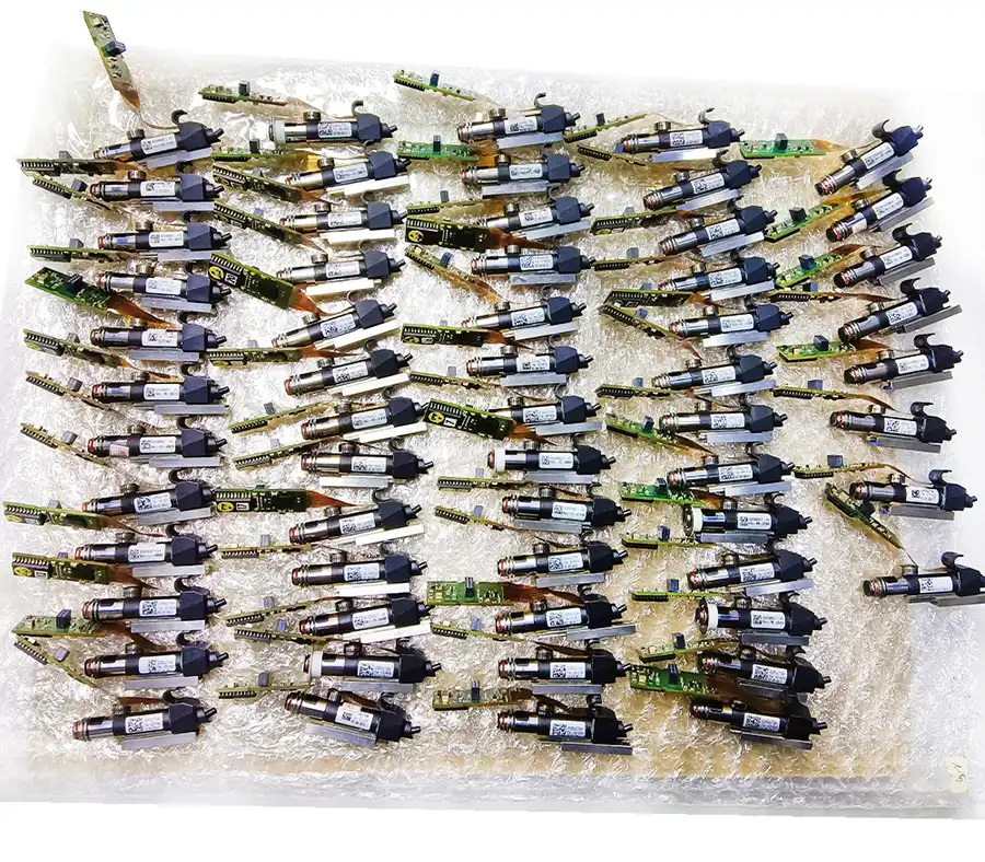
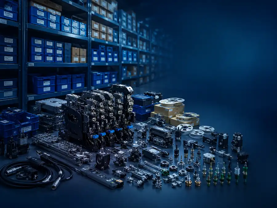
Identify a SIPLACE camera or sensor by its role, complete part number, revision, installation position, and connection details. Camera checks also need the optical configuration and supported image interface. Sensor checks need the detection function and electrical characteristics. A matching case or plug does not establish equivalent operation.
A machine reports a component recognition problem. The camera becomes an obvious suspect, but the observed image can also reflect lighting, optics, contamination, component presentation, or settings. Ordering immediately from a photograph of the camera housing can leave both the fault and the replacement identity unresolved.
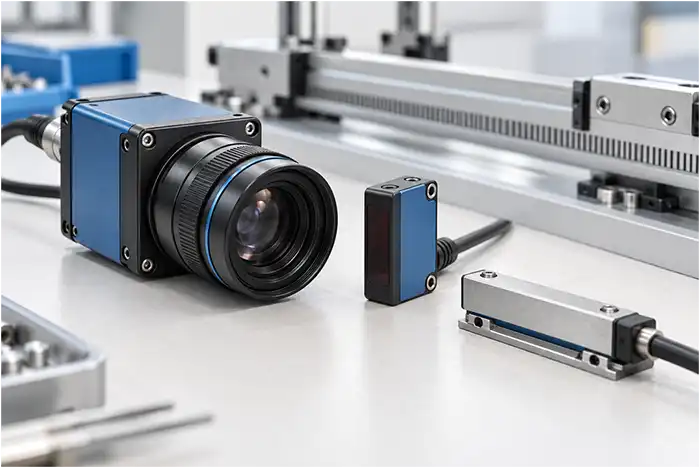
First name the job the device performs
Record whether the device observes a component, a PCB reference, an axis position, or another machine condition. Use the name shown in the machine documentation and include the associated head or subsystem.
Component cameras and PCB cameras serve different observation tasks. Presence sensors, pressure sensors, and encoder reading heads also measure different things, even when a marketplace groups them all under “SIPLACE sensors.” A role description narrows the part request before anyone compares dimensions.
Add a photograph that shows the device in its installed position. Cable routing, illumination hardware, and nearby mounting features can help distinguish assemblies that look similar on a workbench.
Camera identity includes the optical assembly
Copy the complete camera label and photograph any lens, optical module, or illumination identification that can be accessed under the service procedure. Confirm whether the order concerns the camera alone or a complete assembly with optics, mount, lighting, and cable.
The required field of view, working distance, image characteristics, and mechanical alignment depend on the installed optical arrangement. A camera body that fits the bracket can still produce an unsuitable image if the retained optics or image interface do not match the replacement requirements.
Do not approve a camera from the interface name alone
An interface description such as GigE narrows one part of the comparison. It does not establish the complete camera specification or prove support by the machine software. Check the exact assembly, revision, configuration, and any replacement instructions.
When an older and newer camera version differ, ask whether a documented conversion exists. A cable change by itself does not establish that an image format, driver, illumination arrangement, or calibration procedure is supported.
Preserve the calibration requirement in the order
Camera replacement can require alignment, calibration, or configuration according to the machine's service instructions. Establish those requirements before purchase. Include any necessary fixtures or service access in the repair plan rather than discovering them when the part arrives.
A supplier can confirm the identity and supply scope of a camera without having validated the final optical performance in the buyer's machine. Keep those two statements distinct in the acceptance record.
A sensor label must be connected to its measurement
For a discrete sensor, record the detection role, mounting arrangement, sensing direction, operating gap, supply requirements, output characteristics, and connector wiring as specified in the documentation. Preserve the complete manufacturer and machine assembly numbers where both are present.
A connector with the right number of contacts does not establish the correct pin assignment or output. A matching body size does not establish sensing range or response. Check these characteristics against the target circuit and mechanism before connecting a substitute.
For a pressure or vacuum sensor, the pressure range, reference type, output, port arrangement, and machine support may matter. Avoid selecting a replacement solely because the pneumatic connection fits.
Treat encoder reading heads as part of a measuring system
An encoder reading head must work with the corresponding scale or measuring element and the supported signal interface. Its mounting, alignment, and required gap also belong to the system requirements.
Record the axis designation, reading-head identification, scale information where available, cable details, and assembly position. Do not infer interchangeability from an X-axis or Y-axis label in a listing. The same short axis description can refer to different measuring systems across machine configurations.
Where a replacement affects alignment or calibration, use the prescribed procedure and specified tools. A reading head that physically mounts may still require checks that photographs cannot provide.
Capture the fault before changing the device
Save the exact alarm, relevant machine logs, and image examples when available. State whether the failure is constant, intermittent, related to motion, or limited to one component or job. Include recent cleaning, maintenance, or configuration changes.
For a vision issue, note whether the image is missing, unstable, blurred, poorly illuminated, or rejected despite appearing clear. Those descriptions lead to different investigations. For a sensor, record the observed input state and the condition that should change it, following the approved diagnostic procedure.
Do not adjust several optical or detection settings while replacing the part without recording them. That makes it difficult to distinguish a hardware correction from a configuration change.
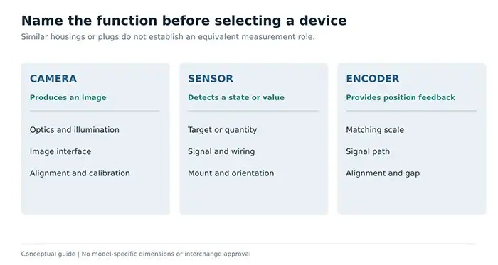
Use the image symptom to frame the camera inquiry
A missing image, a blurred image, and a clear image that fails recognition are different observations. Record which occurs before changing parts or settings. A camera replacement inquiry should describe the observed output alongside the device identity.
Observation | Evidence that helps the investigation |
No image reaches the machine display | Device identity, connection path, recognition status, exact messages |
Image is present but blurred or uneven | Example image, optics identification, illumination arrangement, recent changes |
Image is clear but the component is rejected | Component drawing, job settings, pickup presentation, representative images |
Image fails intermittently during motion | Position or timing pattern, cable route, logs, unchanged settings |
Problem begins after an assembly swap | Original and replacement labels, retained optics, configuration and calibration records |
These observations direct information gathering. They do not assign a failed component. A motion-related image interruption, for example, may justify investigating a connection path without proving that the cable is the cause.
Separate stationary cameras from head-mounted assemblies
The camera's installation role is useful identification information. A camera fixed at a station and a camera carried by a moving assembly can require different mounts, cable routes, and optical arrangements. Preserve the service designation and installed view instead of reducing both to component camera.
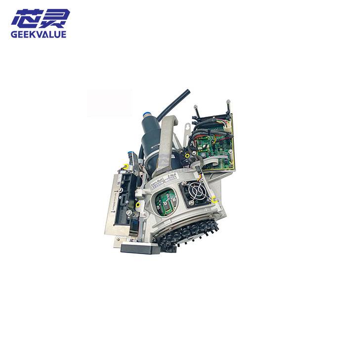
The 03016339 SST33 stationary P+P camera listing provides one specific identity to reference. Its listing name should not be generalized into an interchange rule for other cameras with similar type descriptions. Compare the installed assembly and any proposed replacement through the appropriate technical reference.
Check what a camera-only price leaves out
A quotation may cover only the camera, or it may include optics, illumination, mounting hardware, and a connecting cable. Ask which retained components the offered item expects to work with. If a lens or optical module must be transferred, establish that the combination is supported and that its condition is acceptable.
The same reasoning applies when a SIPLACE placement head is supplied without its original camera. Confirming the head identity does not complete the camera selection. Keep camera inclusion and optical compatibility visible in the head quotation.
Identify sensors by the condition they must detect
For a switching sensor, describe the target and the state change expected at the machine input. For a measuring sensor, describe the quantity and the documented signal requirements. This keeps presence detection, pressure measurement, and position feedback from being grouped together under an imprecise sensor description.
Record the sensing orientation and bracket arrangement before removal. If an adjustment range or operating gap is required, obtain the specified value from the relevant documentation. Do not set it from a photograph of another machine.
A replacement sensor inquiry needs both sides of the interface
One side concerns the physical target or pressure connection. The other concerns power, wiring, output, and the receiving control interface. A substitute needs to satisfy both. A connector that fits and a sensor that switches on a bench are useful observations, but they do not establish the correct operating behavior in the machine.
For an encoder reading head, include the matching scale and the supported signal path. A short description such as axis sensor leaves out the information needed to distinguish a measuring-system component from a simple end-position detector.
Record the result of alignment and calibration
After installation, retain the configuration and calibration records called for by the service procedure. State what was checked and whether it passed. If the machine recognizes the device but the relevant image or measurement remains unacceptable, keep the repair open.
For unidentified sensors or optical subassemblies, the SMT spare parts finder accepts the identification context needed to narrow a candidate. The ASM parts identification guides provide the wider process when labels, previous orders, and installed hardware disagree.
Request evidence that matches the function
A camera test should identify the unit and explain what was checked. An image captured on a bench can show image output under that setup; it does not establish the target machine's recognition accuracy or calibration.
For a sensor, ask which switching or measurement behavior was evaluated and under what conditions. “Tested” has little purchasing value unless the result is tied to the function needed on the machine.
We welcome the label, installed view, and fault description together when reviewing camera and sensor inquiries. If the optical or electrical configuration remains uncertain, identify that uncertainty before selecting a substitute.
Can a camera with higher resolution replace the original
Higher resolution alone does not establish compatibility. The machine must support the camera and its image handling, optics, timing, and configuration. Confirm a documented replacement or conversion arrangement.
Should a dirty lens or sensor face trigger an immediate part order
Assess the condition using the approved inspection and cleaning procedure first. Contamination can affect performance, but cleaning does not resolve physical damage, electrical failure, or an incorrect configuration. Record the outcome before deciding what to replace.