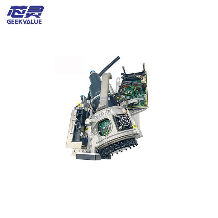
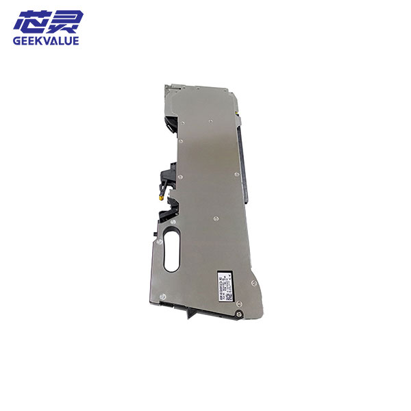
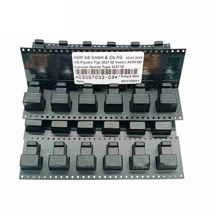
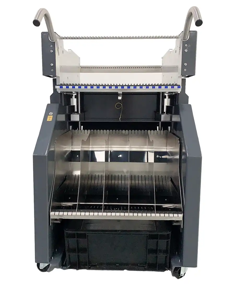
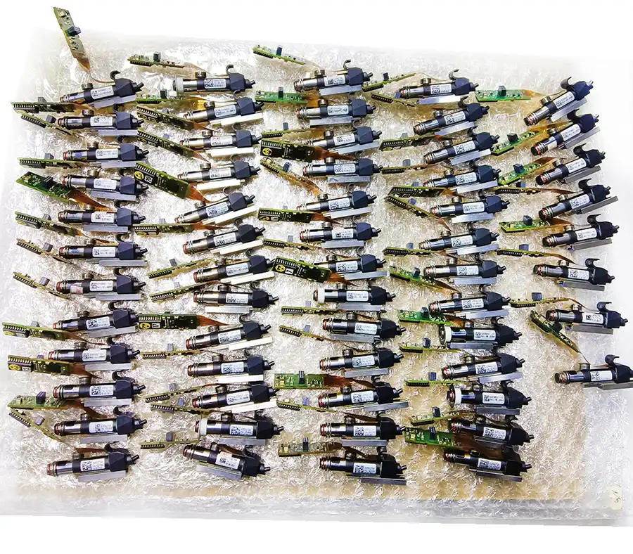
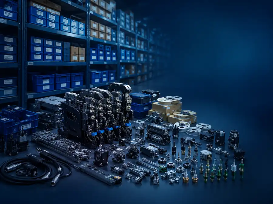
Used ASM SIPLACE CA2 for direct-wafer die attach, flip chip and SMT production. Reduce separate die-handling steps while matching wafer, accuracy and conveyor configuration.
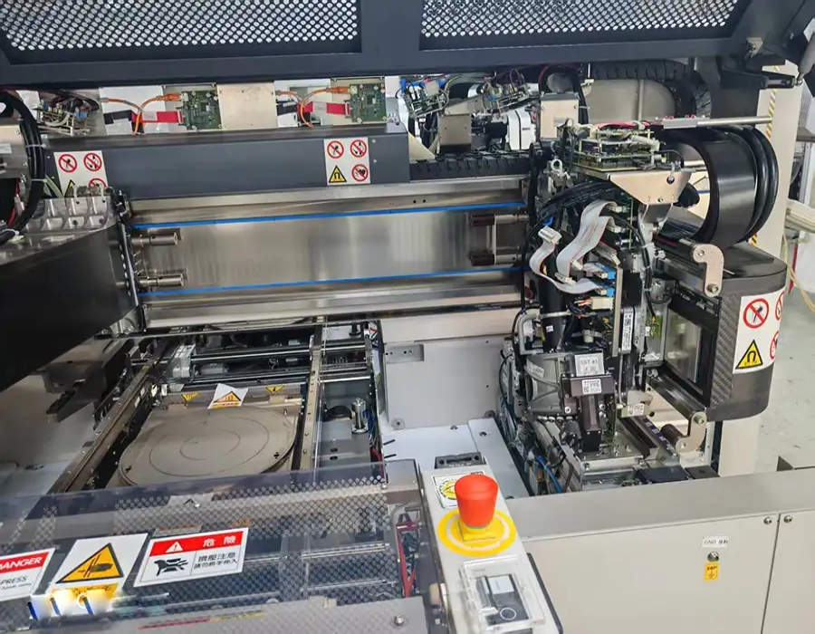
When the same product contains conventional SMDs and bare semiconductor dies, separating SMT placement and die bonding creates costs that do not appear in the machine CPH figure. Dies may need additional preparation, material handling and quality control before they even reach the placement process, while two production stages add more equipment, scheduling and traceability work. The SIPLACE CA2 was developed to remove that gap by combining feeder-based SMT placement with die attach and flip-chip processing directly from the wafer.
This is the main reason to buy a CA2. The platform reaches published benchmark rates of up to 76,000 CPH for SMT placement, 54,000 dies per hour for die attach and 51,000 dies per hour for flip chip, but its strongest business case is not the sum of those numbers. Direct-wafer placement can eliminate the die-taping process for applicable products, reducing replenishment, splicing, tape handling and the associated quality and disposal work.
The platform is designed for System-in-Package, wafer-level and panel-level packaging, embedded PCB and power-semiconductor applications. Its wafer exchange system can manage up to 50 different wafers with a reference swap time of about 13 seconds, while single-die traceability follows each die from its original wafer position to the final placement location. This gives the factory one coordinated process instead of having to reconnect wafer data and SMT production across separate equipment.
For a factory entering or expanding this type of hybrid production, a suitable used CA2 can reduce the capital required to obtain the process capability compared with purchasing an entirely new system. That advantage only exists when the used unit already has the correct wafer system, accuracy class, conveyor and process options. The CA2 is a strong fit when direct-wafer placement removes a real recurring production step; it is unnecessary complexity when the factory only needs conventional packaged-component SMT or already has a separate die-bonding process that works economically for the product.
| Parameter | Reference Specification |
|---|---|
| Machine Type | Hybrid SMT placement and direct-wafer die-bonding platform |
| Placement Head | SIPLACE CP20 |
| SMT Benchmark Speed | Up to 76,000 CPH |
| Die Attach from Wafer | Up to 54,000 dies per hour |
| Flip Chip from Wafer | Up to 51,000 dies per hour |
| Placement Accuracy | 20 µm, 15 µm or 10 µm at 3σ, depending on selected process and accuracy class |
| Tape-and-Reel Component Range | 0201 metric to approximately 8.2 × 8.2 mm |
| Wafer Component Range | Approximately 0.3 × 0.3 mm to 8.2 × 8.2 mm |
| Wafer Capacity | Up to 50 different wafers with the Wafer Exchange Unit |
| Wafer Swap Time | Approximately 13 seconds |
| Feeder-Focused Configuration | Up to 80 × 8 mm tape-and-reel feeder slots |
| Hybrid Material Configuration | Up to 2 × Multi Wafer System plus 10 × 8 mm tape-and-reel feeder slots |
| Single-Lane Substrate Format | Up to approximately 700 × 620 mm at 20 µm and 15 µm classes; 10 µm applications are specified up to approximately 300 × 300 mm |
| Dual-Lane Substrate Format | Up to approximately 375 × 260 mm at 20 µm; smaller formats apply at higher accuracy classes |
| Cleanroom / Compliance | ISO Class 7; SEMI S2/S8 compliant |
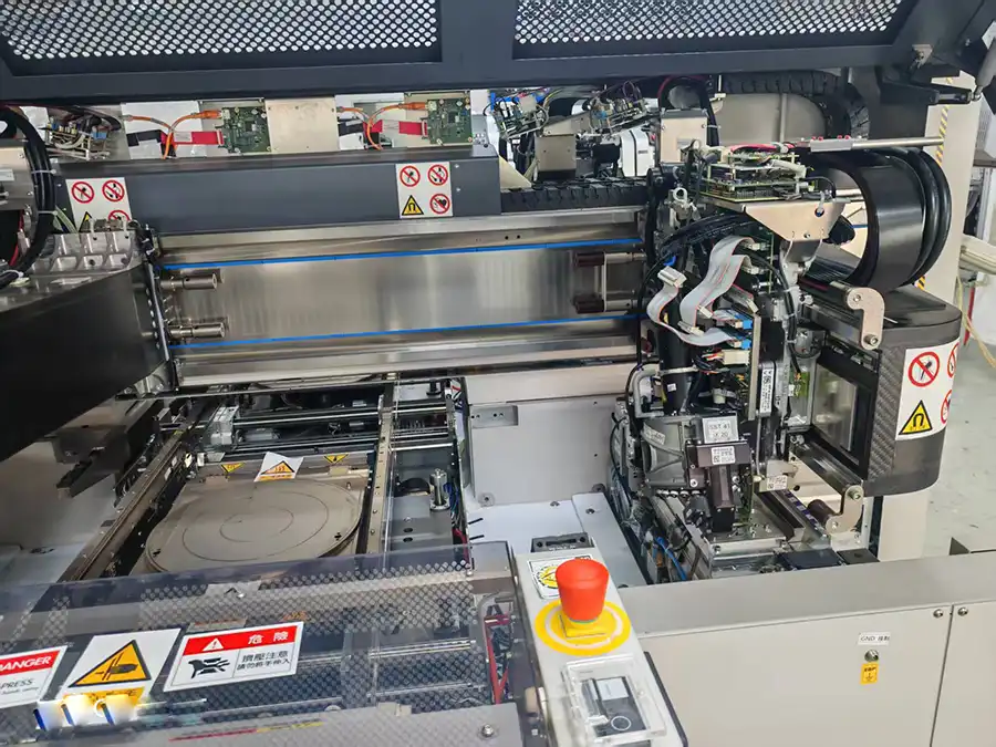
These figures describe OEM reference configurations. The feeder-focused and wafer-focused setups are alternatives, not capacities that should be added together: ASMPT specifies up to 80 × 8 mm feeder slots, or up to two Multi Wafer Systems with 10 additional 8 mm feeder slots. Accuracy class also changes the supported substrate format, so those items must be confirmed on the actual used machine.
The real CA2 buying decision is whether an integrated process removes enough recurring work to justify the machine. If direct-wafer handling eliminates steps that the factory currently performs on every production batch, the value extends far beyond placement speed.
| Buying Factor | SIPLACE CA2 Integrated Process | Separate SMT + Die-Bonding Flow |
|---|---|---|
| Bare-Die Supply | Dies can be placed directly from sawn wafers | Uses a separate die-handling route and may require additional material preparation |
| Packaged Components | Tape-and-reel SMDs can be processed on the same platform | Handled by a separate SMT placement machine |
| Die Taping | Can be eliminated for applicable direct-wafer products | May remain part of the material-preparation flow |
| Process Handoffs | Fewer transfers between die processing and SMT placement | More movement and scheduling between separate equipment |
| Traceability | Single-die data can follow the die from wafer position to final placement | Data must be coordinated across separate process systems |
| Best Fit | SiP and advanced-packaging products that genuinely combine bare dies and packaged SMDs | Factories where dedicated SMT and die-bonding processes are already efficient and intentionally separated |
This comparison is also the financial test. The used-machine price is only one part of the decision. The stronger CA2 business case exists when the factory can repeatedly remove die taping, extra material handling, process transfers or separate equipment requirements from the production flow. If those costs do not exist in the current process, buying a hybrid machine simply because its specification is impressive does not create value.
For a used CA2, we would compare machines only after confirming the Multi Wafer System, CP20 head configuration, accuracy class, cameras, conveyor, dipping and inspection options, software and feeder package. A lower-priced unit with the wrong accuracy or wafer configuration can create more conversion cost than it saves in the purchase.
The CA2 is therefore strongest when the factory is buying a simpler production flow, not merely another high-spec placement machine. If the main requirement is to preserve an already qualified older CA production process rather than redesign it, a correctly configured SIPLACE CA4 may still be the more economical replacement choice. Explore the wider SIPLACE CA Series when the decision is still between process architectures.
If you are not sure whether this product matches your machine, send us the model, label photo or old part picture for checking.