
Match SIPLACE belts, cables, and mechanical spares by their complete assembly identification and the dimensions or interfaces that control operation. Belts need the correct profile and construction. Cables need verified wiring and motion requirements. Guides and blocks need the correct mating geometry and mounting orientation. Overall size is only a starting point.
These parts often arrive in purchasing with an incomplete description: “black timing belt,” “camera cable,” or “small sliding block.” They appear straightforward because their main features are visible. The details that govern operation can be harder to see, especially when the original item is stretched, worn, or damaged.
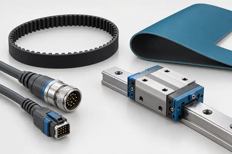
A belt photograph cannot establish the tooth profile
Begin with the complete part number and any readable belt markings. Identify whether the belt transmits motion through teeth, transports a PCB through friction, or performs another function. A toothed drive belt and a flat conveyor belt need different comparison fields.
For a timing belt, verify the specified tooth profile, pitch, tooth count or pitch length, width, and construction. Similar tooth spacing does not guarantee the same tooth shape or pulley engagement. Color provides little useful evidence of compatibility.
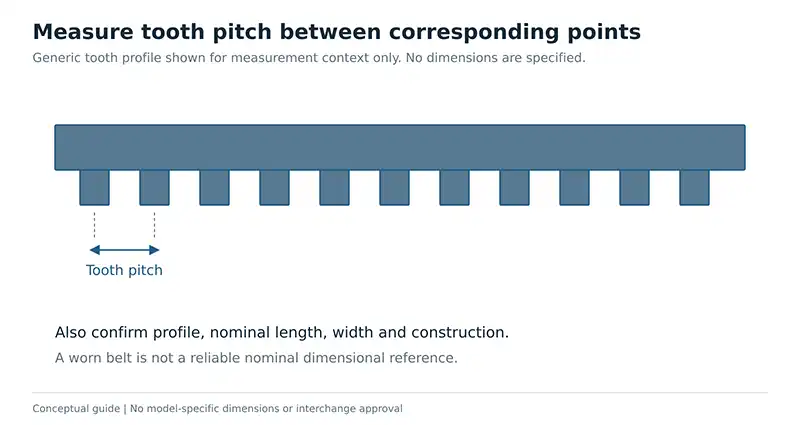
If pitch is uncertain, a technician can measure across several intervals under an appropriate measurement method. The result can help distinguish candidates, but the nominal specification should come from the part record or belt documentation. A worn belt is a poor dimensional master.
Conveyor belts need a different comparison
For a flat transport belt, check the specified length, width, thickness, surface, construction, and joint arrangement where relevant. The transport path, roller geometry, and required grip affect the choice.
An old belt may have stretched or worn. Copying its current length can reproduce the wrong specification. Identify the original nominal belt or the documented replacement assembly and confirm the tensioning or installation requirements in the machine procedure.
Describe a cable by its endpoints
“SIPLACE camera cable” names a broad function. “Cable between the identified camera assembly and the identified controller connection” gives the supplier a traceable relationship. Photograph both endpoints, including connector designations visible on the machine.
Capture connector faces, key positions, locking features, backshells, strain relief, and the label on the cable. State the overall length and how it was measured. Record any branches, intermediate connections, grounding attachments, or protective sleeving.
Matching plugs do not prove matching wiring
Two cable assemblies can share connector shells and still differ in contact assignment, shielding, pair arrangement, or electrical characteristics. Use the documented assembly number and wiring specification to resolve the match.
Do not validate an unknown cable by plugging it into the machine. Electrical checks should follow the approved procedure and protect connected electronics. A continuity result alone cannot establish every performance requirement of a data, feedback, or other specialized cable.
Moving cables need the right construction and route
A cable inside a moving carrier operates under different conditions from one fixed inside a cabinet. Check the documented flexing or torsion requirements, bend limits, shield arrangement, and environmental conditions relevant to the installation.
The route matters after the correct cable has been selected. A cable installed with insufficient movement allowance or unsuitable clamping can suffer strain at the connector or a tight bend. Preserve the specified routing, retention, and separation from moving mechanisms.
Include the cable's installed path in the inquiry when motion is involved. A photograph of two loose connectors cannot show whether the requested cable must pass through a carrier, reach a moving head, or include fixed mounting points.
Sliding blocks and belt guides must match their mating parts
For a sliding block, check the rail or mating guide, mounting-hole pattern, envelope, orientation, and specified accuracy or preload details where relevant. Similar outside dimensions do not establish compatibility with the retained rail.
For a belt guide, compare the belt contact geometry, mounting references, offsets, and running direction. Small differences in guide position can affect tracking or clearance even when the part bolts into place.
Photograph the assembly before removal and retain any spacers, shims, or locating details according to the service procedure. If wear has changed a contact surface, identify the nominal geometry through documentation rather than reproducing the worn shape.
Resolve the hidden detail for each part type
Part type | Visible match to check | Detail that still needs confirmation |
Timing belt | Width, markings, tooth count | Tooth profile, nominal pitch length, construction |
Transport belt | Width, path, surface | Nominal dimensions, material, joint and installation requirements |
Cable assembly | End connectors, branches, length | Wiring, shielding, signal and motion requirements |
Sliding block | Mounting pattern, outside dimensions | Mating rail, specified fit, preload or accuracy where relevant |
Belt guide | Mounting points, contact surface | Offset, orientation, belt engagement and clearances |
Record nominal dimensions separately from worn measurements
A removed part gives useful physical evidence, but its present dimensions may reflect service wear. Keep the measured value and the nominal specification in separate fields. Mark whether a number came from a drawing, a readable manufacturer marking, an unworn reference, or the damaged item.
For a timing belt, pitch length differs from a casual outside-circumference measurement. If a confirmed belt specification gives 100 teeth at 3 mm pitch, the pitch length is 300 mm. This arithmetic example does not identify the tooth profile, width, construction, or a SIPLACE ordering number. Those requirements still need confirmation.
For a flat conveyor belt, the relevant length and installation allowance depend on its specified construction and transport arrangement. Avoid applying the timing-belt calculation to a flat belt or adding a guessed stretch allowance to the measured length.
Use photographs that show the measurement reference
A ruler beside a cable or belt gives scale, while a clearly marked dimension states the required fit. Show where the measurement begins and ends. For cables, identify whether the value includes connectors, backshells, branches, or only the flexible section.
For a bracket, guide, or sliding block, show mounting-hole centers and the mating face. Record orientation relative to the machine. Left and right descriptions become ambiguous once an assembly is loose on the workbench, so retain an installed view with its machine position.
When comparing a named item such as the 03020301 X-axis linear guide carriage, use the complete label and parent mechanism alongside the dimensional check. A catalog photograph cannot establish the internal fit or condition of the supplied carriage.
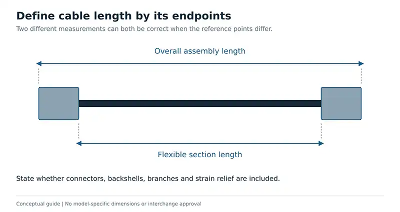
Figure 6.3 A cable length is meaningful only when its endpoints and included hardware are defined.
Separate cable assemblies from loose connectors
An inquiry for a cable assembly should include its full wiring and mechanical scope. Confirm whether the offered item includes branches, protective sleeves, grounding points, mounting clips, and strain relief required by the installed route. A plug kit or connector pair does not provide that complete assembly.
If the original cable was repaired, identify which details remain original and which were changed. A replacement copied from an undocumented repair can preserve a wiring or routing error. Compare the machine record and approved cable specification before reproducing the altered assembly.
Why a longer cable needs review
Extra length must be accommodated without creating an unsuitable bend, obstruction, or strain at a termination. The electrical interface may also impose length or construction requirements. The correct solution depends on the specified assembly and route.
For motion-related wiring, include the associated mechanism in the request. The SIPLACE motor and feedback parts range helps distinguish a motor assembly request from a cable or feedback-component request without assuming that all three must be replaced.
Compare mechanical spare quotations by the mating interface
Ask whether a guide or block is supplied alone, as a matched set, or within a larger service assembly. Confirm which existing rail, belt, shaft, or mounting surface remains in service. The retained hardware creates requirements the replacement must meet.
Do not combine an arbitrary block and rail because the mounting-hole pattern matches. Where preload, accuracy, or fit is specified, retain those requirements in the quotation. If a supplier offers a different assembly level, compare the work required to complete the repair.
Store identification data with the spare
Receiving records should retain the complete number, nominal specification, accepted condition, and target machine. Keep belts, cables, and precision mechanical parts in the packaging and storage conditions appropriate to their documentation. Do not use an improvised bend or hanging arrangement that could damage a stored item.
After a verified installation, update the machine's spare-parts record with the accepted replacement identity and any routing or configuration reference. The ASM SIPLACE spare parts catalog can then be approached with an established requirement rather than another photograph of an unidentified damaged part. Where the ordering number is still missing, submit the measurement references and mating-part images through the SMT spare parts finder.
Check the cause of damage before fitting the spare
A replacement belt can fail again if tracking, pulley condition, or tension remains wrong. A new cable can suffer the same damage if the carrier or clamp continues to pinch it. A replacement guide can wear quickly if the retained mating surface is damaged.
Use the machine's inspection procedure to evaluate the related mechanism. Record any corrective work separately from the replacement part number. That creates a useful maintenance history and avoids attributing every repeat failure to the spare itself.
After installation, follow the prescribed tension, routing, alignment, or movement checks. Validate the relevant transport or motion function before production release. Keep the accepted replacement identity with the machine record so the next order starts with confirmed information.
We encourage buyers to include the mating part and installed route in photographs of mechanical and cable requests. Those views often answer questions that the loose spare cannot, particularly when its label is missing or a previous repair changed the arrangement.
Can a longer cable replace the original if the connectors match
Length changes can affect routing and, for some interfaces, electrical performance. Confirm the supported assembly and installation arrangement. Avoid leaving an unplanned loop near moving components.
Can belt measurements replace a missing part number
They can help identify candidates, especially when markings and pulley information are available. Confirm the nominal specification and required construction before purchase. A stretched or damaged belt alone may not provide enough evidence.