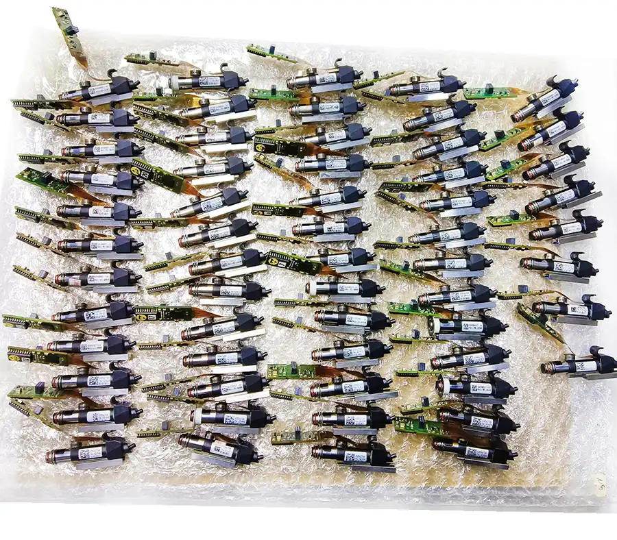
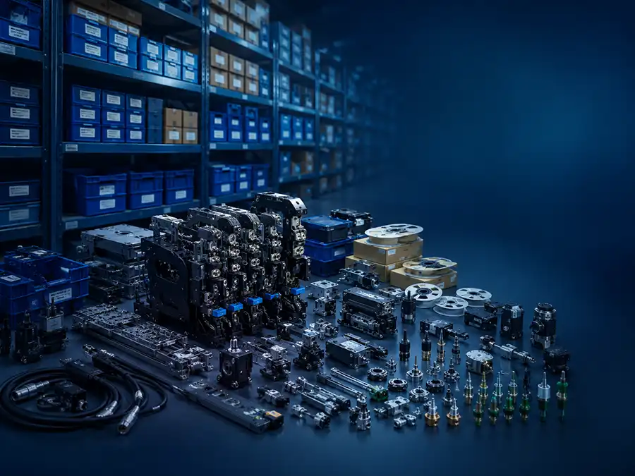
Used Siemens SIPLACE D3 three-gantry SMT mounter with C&P12, C&P6 and TwinHead options for mixed SMD, IC and large-component production.
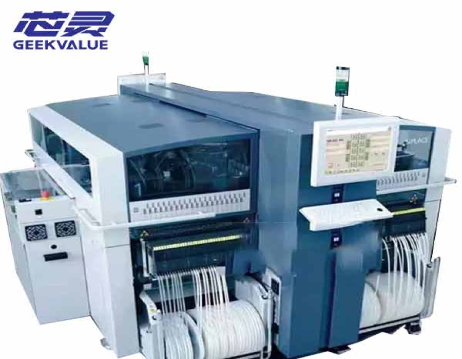
For factories that need to increase placement capacity without giving up flexibility for mixed-component production, a used Siemens SIPLACE D3 is a practical three-gantry option. We can provide D3 machines in different C&P12, C&P6 and TwinHead configurations, so buyers can select the available unit around the actual PCB and BOM instead of adapting production to an unsuitable head combination.
With three C&P12 heads, the D3 is rated at 37,600 CPH under IPC 9850 conditions and 40,400 CPH under the SIPLACE benchmark, with a theoretical maximum of 61,000 CPH. More importantly, the three gantries can be configured for different placement tasks. C&P heads handle standard SMDs and IC packages efficiently, while a TwinHead configuration extends the machine toward larger, fine-pitch or more demanding components. This allows the D3 to add usable placement capacity while keeping a broader part of the BOM on the same machine.
For high-mix EMS, industrial control, communications and other PCB production with a wide component range, this flexibility can reduce the need to divide work across several placement stages. The platform also supports up to 180 feeder tracks with the applicable feeder-table setup, giving factories enough material capacity for component-dense boards and frequent product changes. For plants already operating SIPLACE D Series equipment, the D3 can also be considered for capacity expansion or replacement while retaining a familiar production environment.
The D3 is best suited to factories that need both higher placement capacity and flexibility across different component types. It is less suitable when production is almost entirely made up of small standard components and the only objective is maximum chip-placement throughput. Published CPH figures are OEM reference values rather than guaranteed output for an individual used machine. Actual performance depends on head condition, calibration, feeder setup, PCB program and overall machine condition, so the selected unit should be evaluated with configuration records and a powered-on placement test where available.
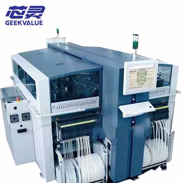
| Parameter | Reference Specification |
|---|---|
| Machine Type | Three-gantry SMT placement machine |
| Gantries | 3 |
| Placement Head Options | C&P12, C&P6 and SIPLACE TwinHead |
| Maximum IPC 9850 Rate | 37,600 CPH with 3 × C&P12 |
| Maximum SIPLACE Benchmark | 40,400 CPH with 3 × C&P12 |
| Theoretical Maximum | 61,000 CPH with 3 × C&P12 |
| Documented Component Range | Approximately 0201 to 200 × 125 mm, depending on the installed heads, cameras and tooling |
| Feeder Capacity | Up to 180 tracks with compatible 3 × 8 mm S feeder modules |
| Component Changeover Tables | Up to 4 |
| Maximum PCB Format | Up to approximately 610 × 508 mm with the required conveyor options |
| PCB Thickness | Approximately 0.3–4.5 mm as standard |
| Maximum PCB Weight | Approximately 3 kg |
| Conveyor Options | Single conveyor or flexible dual conveyor |
The largest component sizes require a suitable TwinHead setup, while the highest published speed applies to the three-C&P12 configuration. These limits should not be combined and treated as the capability of every used D3.
| Head Configuration | SIPLACE Benchmark | Production Fit |
|---|---|---|
| 3 × C&P12 | 40,400 CPH | High component counts dominated by standard SMDs and compatible IC packages |
| 2 × C&P12 + C&P6 | 36,200 CPH | High standard-component output with additional coverage for larger IC packages |
| 2 × C&P12 + TwinHead | 31,400 CPH | Standard SMD production combined with connectors, fine-pitch or special components |
| C&P12 + C&P6 + TwinHead | 25,300 CPH | High-mix boards where three different placement functions all have meaningful work |
A lower benchmark does not automatically make a D3 configuration less useful. If the installed heads allow more of the PCB to be completed on the same machine, the factory may avoid shifting component groups to another placement stage and achieve a better-balanced line.
For the selected used D3, the final decision should be based on the actual head labels, feeder package, conveyor configuration and machine condition. Current machine photos, available inspection records and powered-on test evidence should be reviewed before the delivery scope is finalized.
If you are not sure whether this product matches your machine, send us the model, label photo or old part picture for checking.